Pacman: Installing a 15 Amp Power Supply
Like I Said before I love the 15 amp power supplies! They are very easy to install and if they go bad then you can just replace it for around 20 dollars or so.
A.) If your game already has a 15 Amp power supply inside it, then Lets First trouble shoot it. If it has an old power supply and you may wish to install a new 15 amp then skip below to B.)
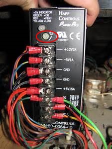
First, as written in the Fuse and Power Post locate the LED light on The power supply.
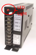
If it’s On when the power of the game is plugged in and on then take an Ohm reader and put the setting on VAC.
This will read the AC (Alternating Current) Volts. Set the Ohm reader on the 200VAC setting and then start with your wall socket plug. Stick one metal end on the right side of the plug and the other in the left socket and you should be reading between 110AC to 120 AC coming from the wall. Next, read the voltage on your power supply at the Power inputs as per shown below.
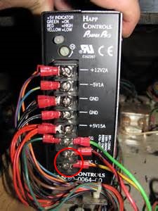
This could be different on your power supply! Just find the Label of AC Input.
Again with your Ohm Reader set to the 200VAC setting find on your power supply where the 110AC is hooked up to the power supply.
Place one of your multimeter leads on each of the terminals marked AC on your power supply. As we stated before, you should read somewhere around 120 VAC. If your multimeter does not read around 120 VAC, it’s time to start tracing down your wiring to see what the problem is. Has the power has to be interrupted between the wall socket and power supply, so narrow down the search until you’ve found the break in the AC current. A reading of 0 VAC is a good indication that there is no AC voltage going to your power supply.
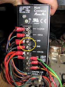
Now that we have checked your AC voltage and verified that it was correct, we can now test your DC (Direct Current) voltage. DC voltage is what powers your board, controls, and coin door lights among other things. In order to test our DC voltage, You will need to set your multimeter to VDC. We will be checking voltages around 5 and 12 VDC so a good setting on your multimeter would be 20 VDC. Once you have your multimeter set, it’s time to test our 5 VDC. Place your black lead on the common (or ground) terminal and place your red lead on the +5 VDC terminal. You should get a reading that’s around 5 VDC. Keep that reading in mind while we test the 12 VDC. While keeping your black lead on the common (or ground), move the red lead to the +12 VDC terminal and keep this number in mind as well.
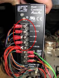
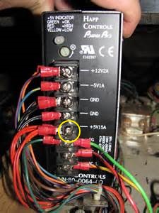
After reading the 5 VDC and 12 VDC, you might realize that these numbers are a little bit higher or lower than what they are suppose to be. You might have noticed a knob on the power supply. This knob controls the DC voltage output.
Turning the knob right or left can increase or decrease the amount of DC voltage coming out of the power supply. Turn this knob to the right or left and test your 5 VDC and 12 VDC to see if they are closer to the correct voltage than before. If you are coordinated, you can test the voltage while turning the knob but either way should be fine. Once you are satisfied with the DC voltage output, turn the arcade game off, plug in your board and turn it back on.
If you try and turn the knob but you can’t seem to get both the 5 VDC and 12 VDC close enough then you might need a new power supply and this might very well fix your game. Once you’ve received a new power supply keep reading below.Replacing a power supply is easy. First, make sure the game is unplugged. Then, remove the wires from the terminals on the existing power supply and place them on the matching terminals of the new power supply. You might want to label the wires as you take them off so you can make sure you put them on the correct terminals of the new power supply. Placing the wrong voltage on the wrong terminal can have dire consequences for your arcade game! Once you have done this, you have successfully replaced a power supply.
B.) Replacing the Old power supply with a new 15 amp power supply.
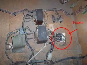
If your power supply looks like this above then its a good time to replace it completely with a new 15 Amp Power supply.
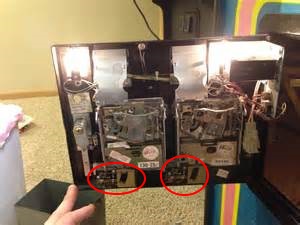
First thing to do is Unplug your Game! Next, Locate the two wires coming from the isolation transformer supplying power to the monitor.
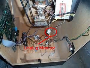
I like to splice into these two wires to get my 110VAC from here to power the new 15 amp Power supply. What you will need to do is with the power again unplugged! Right below the Molex connector shown above that supplies the 110 AC power to the monitor, we’re gonna splice into each of these two wires and run another wire over to the new power supply in order for it to be able to receive a source for the 110AC. This also saves time as all the fuses and isolation transformer will still be left in place and still will perform its function. So don’t get rid of anything in your cabinet. It may still have a function for the game. Take the spliced wire from the black wire going to the monitor power chord and hook it up to the AC Input of the power supply. Do the same for the white wire going to the monitor; splice into it and run the spliced wire to the second AC input terminal of the power supply.
Note: all we are doing is stealing the power going to the monitor to power supply. The black spliced monitor wire should be run to just one of the AC inputs on your power supply. The White Spliced monitor wire should go to the other AC input on your power supply. Never hook them to the same AC input! Also Splice the Field Ground (usually green wire) to the field ground of the Power Supply. The power chord to the monitor still needs to supply the monitor with power too. We are just splicing into it, not hooking up the monitor wires to the power supply!
Once you’ve done this, now the power supply will have power. Next you need to look at your jamma wiring harness.
In order to hook up the new wiring harness we must first look at the power DC section of the JAMMA wiring pinouts. Also unplug your old original wiring harness and set it aside.
Proceed as Follows: With all the power off to the game!
Take the Ground wires from JAMMA harness pins 1,2,A,B,27, 28,E,F and hook them up to the grounds of the power supply. Yes you may have to splice some of these together but they ALL need to be hooked up.
Next Take the wires from Pin 3,4,C,D and hook them up to the +5 terminal of the Power Supply.
Next -5 Pins 5,E to the Minus 5(-5) terminal of the power supply.
Next take the +12 at pins 6,F and hook them up to the +12 of the power supply.
Now lets go down the wiring harness pins starting with pin 10 and take that speaker (+) wire and hook it up to the (+) terminal of the speaker. Take Pin L Speaker (-) and hook it up to the other wire coming from the speaker. You may save time by just cutting the wire in place below where it is already soldered in to the speaker and splicing the new wire in to it. Just make sure the wire is not still receiving power from the Old power supply and any splice please use electrical tape to cover bare wires.
Next for the video output section coming from the Monitor; splice the following:
Pin 12 into the Video Red Wire
Pin 13 into the video Blue Wire
Pin 14 Into the Video Ground (Usually the black wire)
Pin N into Video Green Wire
Next hookup the Pin 16 to the coin slot switch number 1 and Pin T to coin slot switch number 2.
The black wire coming from the coin switch needs to be hooked up to one of the power supplies grounds.
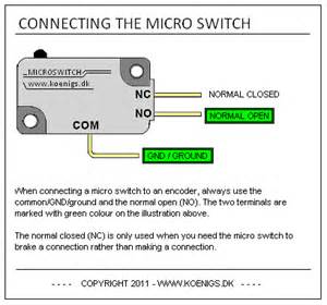
Next hookup Pin 17 to the Player One Start Micro switch. Then Player 2 Pin U to the Player Two Start switch. All Grounds go to a ground terminal from the Neutral/ground switch to the power supply.
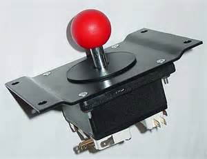
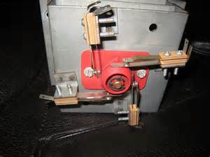
Next for the joy stick:
Or
Pin 18 wire to the Player Up of the Joystick to the Normally Open (NO)Contact terminal of the switch.
Pin 19 wire goes to the Player Down Of the Joystick to the NO contact terminal of the switch.
Pin 20 to the Player Left of the Joystick to the Normally Open (NO)Contact terminal of the switch.
Pin 21 to the Player Right of the Joystick to the Normally Open (NO)Contact terminal of the switch.
For The player Two Pin U-Y hook it up to the same terminals in only using one joystick. If you have a cocktail game then the player two will go to the second joystick.
All grounds can be wired in a series from ground to ground then back to the ground of the power supply.
No other wires or buttons are used for a Pacman game so the other wires will not be used.
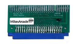
Please double check that everything has been wired correctly. Please note you must buy a
Pac To Jamma adapter in order to plug the 56 pin JAMMA harness to the Original Pacman PCB board.
Once you’ve installed all the above. Plug your game back up and turn it On.
Hopefully Everything is up and running. If Not, just check the the correct pin/wire is going to the correct place and that you have grounded everything.