
![]()
Step Sixteen: How to Install G07 Monitor Cap Kits
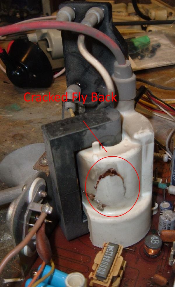
Most Pacman monitors that are wavy or distorted are due to a failure or drying out of the electrolytic capacitors, thus reducing their capacitance. When people don’t fix this with a “cap kit” then what eventually happens is the reduced capacitance stresses on other parts, and the monitor basically implodes. In the process it also takes out the Horizontal output transistor (aka H.O.T.). Notice the HV fly back transformer has a huge crack along its side, and goo has leaked out.
Check the Fuses first.
There are two fuses on the G07 monitor chassis. The one that usually blows (especially when the fly back implodes) is the fuse mounted at the back edge of the chassis board, fuse F902.
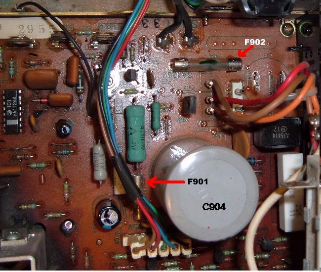
This is a solder-lead style fuse. I don’t suggest using that style. Instead replace it with a PC board mount fuse holder. With all Power Off and Unplugged, you can check the fuse with a Ohm Meter Reader to continuity.
Installing the Cap Kit.
Installing the cap kit is the least fun of any of these tasks. The caps MUST be installed correctly, or you will certainly blow up a reversed cap (and maybe some other components to boot). So don’t get this step wrong.
A capacitor’s longer leg is the positive lead. Negative on the cap is also indicated by a band on the body of the cap, usually with a “–” sign. On the G07 chassis board, negative is indicated on the parts side of the board as a solid dot on the circle indicating where the cap installs. There is often a dot on the solder side of the board too, again indicating the negative lead of the cap.
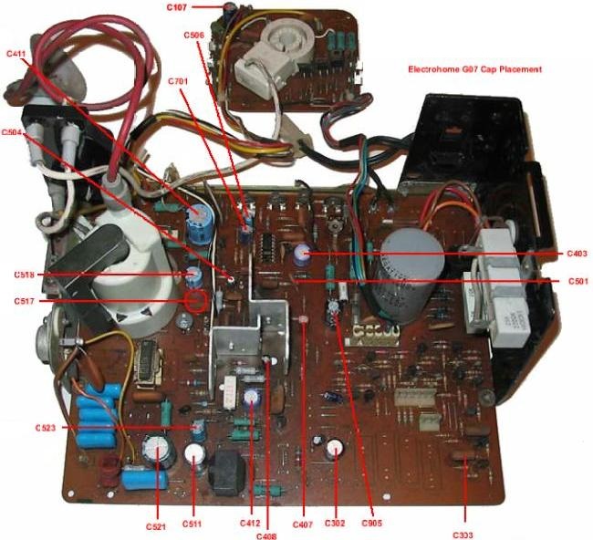
The G07 cap kit should include the following capacitors:
- C506 – 25v 33 mfd
- C403 – 25v 100 mfd
- C517 – 25v 100 mfd
- C701 – 25v 100 mfd
- C302 – 25v 220 mfd *Note* polarity is incorrectly marked on solder side
- C518 – 25v 220 mfd
- C521 – 25v 2200 mfd
- C504 – 50v 1.0 mfd
- C408 – 50v 4.7 mfd
- C303 – 50v 10 mfd *Optional* see note below
- C407 – 63v 4.7 mfd
- C412 – 160v 3.3 mfd
- C511 – 160v 47 mfd
- C411 – 160v 100 mfd
- C523 – 250v 1.0 mfd
- C107 – 250v 10 mfd (Neck board)
- C905 – 250v 10 mfd
- R908 – 47k 1/2 watt resistor
Occasionally cap kits may substitute a higher voltage cap than indicated above. Higher voltage rated caps are fine, but using a lower rated cap is a bad idea (though some kits will do this, because they know a lot more about this monitor than me).
Note that EVERY ELECTROLYTIC CAP EXCEPT THREE get replaced on the G07 monitor chassis board. The only caps that don’t get replace are C301, C520 and C904 (the big cap).
After you have installed all the caps, VISUALLY CHECK from the parts side of the board that you did not install any backwards! I can’t stress this enough – installing a cap backwards will cause an explosion (yes the cap explodes), and this will kill all of your enthusiasm in doing this project.
If you look at a G07 Cap Map you’ll notice that a majority of the negative cap lead “bullets” on the monitor board are facing the front of the chassis or toward the fly back. There are only four that deviate from this pattern, and three of those are under the metal protection shield (missing in all these pictures) and out of sightThere is an optional C303 upgrade. Personally I never do this upgrade (and frankly find no need for it), but some claim it helps with screen “curling” problems. Here are the steps for that modification.
- Remove C501 and discard.
- Remove C303 and install it where C501 was installed.
- Remove the solder from the hole that is in the middle of the two holes where C303 originally resided, and fill the C303 hole farthest from the board’s edge with solder.
- Insert new cap (10 mfd 50v) in the cleaned holes, with the positive lead closest to the edge of the board (to the collector of X305).
- After installation, you may need to adjust the Horizontal Hold. Hole you don’t have to, as the HHold coil is usual pretty fragile from heat stress. Leave it alone if at all possible.
Check or Replace Resistor R908.
The resistor R908, a 47K ohm 1/2 watt resistor (right next to the F902 fuse at the back of the chassis), is often way out of spec. This especially happens if the flyback transformer died. The added strain of a failing flyback puts a lot of stress on this resistor. So at minimum check the resistor, or just replace it. Many cap kits come with this resistor just in case.
Install the Fly back.
Now that all the work is done on the chassis board, it’s time to install the fly back transformer. Don’t forget the two screws that hold the transformer in place. The one wire coming off the fly back (not the suction cup) needs to get attached to the focus/brightness knob tree. I cut the old wire off with about a 1/2″ to give, butt solder the new one wire to the old stub, and then put the new wire hood over the butt connection. A dab of silicon will keep the wire hood in place.
Check the Neck board RGB Transistors.
There are three transistors on the neck board that control the Red-Green-Blue guns inside the monitor tube. If one of these transistors is bad, the monitor will be missing that color (and look really bad). These three transistors are easy to check using a DMM set to diode setting. Replace any questionable transistor. Double Check all Capacitor Installations!
from the parts side of the monitor chassis, give a good look at all the caps and the dots on the board. The dots should line up with the negative band on the caps. A backwards installed electrolytic cap WILL blow up, spewing bits of goo and aluminum all over the place.
Clean Up Your Solder Work.
If you’re not a soldering ace, I would highly suggest taking some dollar store alcohol and a small wire brush (available at Home Depot in the welding department), and clean off all excess flux and other solder junk. This will make inspection of your work much easier. And then you can look for…
Lifted Solder Pads.
Broken solder pads are another typical problem on G07 monitor boards. Since this is a single sided board, the pads lift REALLY easy. This can isolate a freshly installed capacitor from it’s connecting trace. Not a bad idea to use a DMM set to continuity to check all cap pads to make sure they buzz out to their nearest component.
Isolation Transformer: REQUIRED.
This applies to all monitors of this vintage. An isolation transformer (primary 120 volts, secondary 120 volts) IS REQUIRED. You can NOT plug the power cord of a G07 monitor directly into wall 120 volts, it must go through an isolation transformer first. If you power up one of these monitors without an isolation transformer, you are asking for trouble! If you’re lucky, the only damage will be one of the diodes at D901 to D904 is shorted (these are acting like a bridge rectifier). If it got past the bridge, look at the voltage regulator X04 next and beyond (schematics needed).
All Done!
Now re-install the chassis and neck boards into the Electrohome G07 monitor frame. Don’t forget all the connectors (including the ground wire going to the neck board) and the HV flyback electrode. When you power up the monitor for the first time, do it while watching the back of the monitor and the monitor chassis. This way you can see if anything “pops” when power is applied, and quickly unplug the monitor! The new fly back will require you to adjust the focus and brightness knobs mounted to the fly back. The focus is the top most knob (furthest away from the circuit board). Note sometimes the picture can be “weak”. This is another problem with a 30 year old monitor. You need a tube rejuvienator, which is a whole other subject, which won’t be covered here. (What happens is the color guns inside the monitor get covered in crap, and won’t give a good strong picture.)
Return Home
Looking for hard to find Pac/Ms Pac parts for your game? Click here for our Parts for Repair Page
Hi, Great job on this site, I’m able to just open up the pacman mini cabinet and start troubleshooting.
The middle fuse of the group of three fuses on the bottom board blows when I turn on the machine. It doesn’t blow when I unplug the monitor and turn on the machine(sound, buttons, and lights work)
Would it fix the monitor to replace the all the caps on the chassis plus HOT, Flyback Transformer and width coil or might it be something else. Are there replacement monitors, I prefer not to use the lcd.
FYI, I went through your troubleshooting steps and ended up with monitor problems.
Also, the components are covered in a thick kinda of sticky dust, any recommendations to remove this with out causing problem.
Thank you,
Yes sounds like a bad fly back….u can start with that and replace it…or to be safe also replace all caps for sharper pic…or just buy a new G07 equivalent replacement chasis which is sometimes easier..or third u can buy a whole new nonitor
Good information and much appreciated!